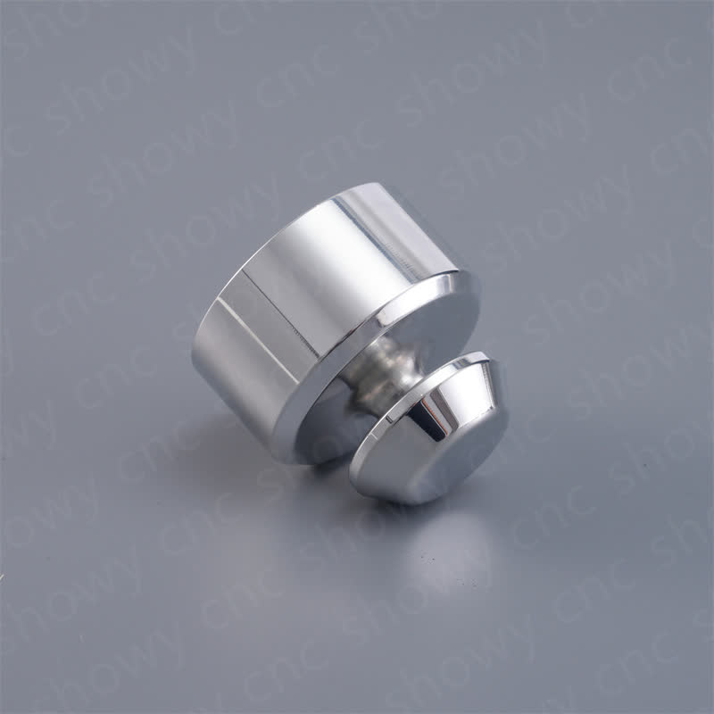


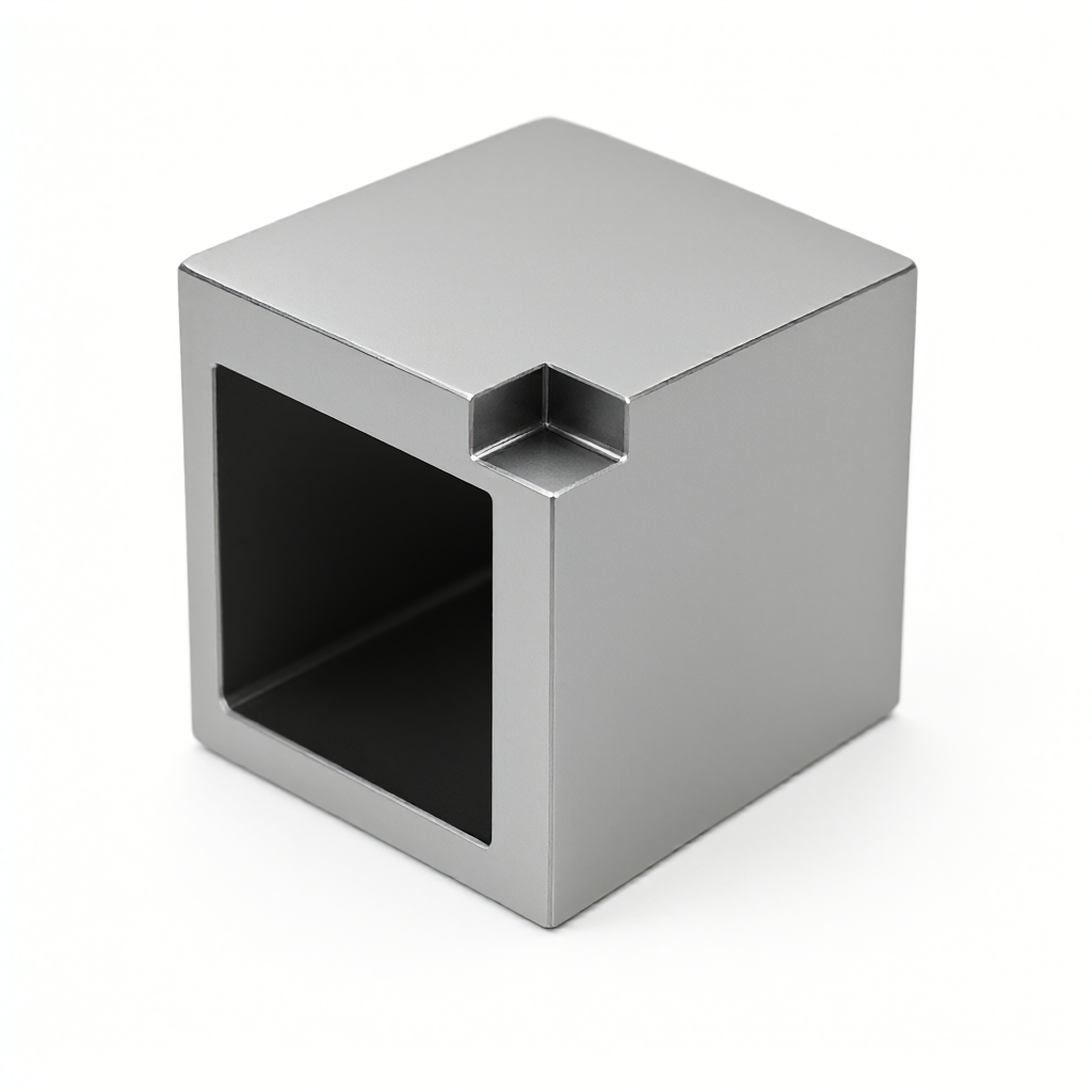
For precision parts such as joint reducer shell with complex structure, thin wall and easy deformation, it is often impossible to meet the rigid requirements and assembly accuracy of transmission system only by casting blank. It is a key step to improve the service life and efficiency of reducer to correct the casting residual flash, riser trace and size tolerance to ±0.01mm by precision CNC deburring and finishing process. Based on ShowyMetal's engineering experience in metal parts customization, this paper explains the technical points of the whole process from incoming material evaluation to three-dimensional final inspection in detail, helping engineers and purchasers to define processing boundaries, process parameters and quality control standards.
Defect Identification of Casting Blank and Necessity of CNC Deburring
Joint reducer shell is usually made of aluminum alloy (such as ADC12, A380) or magnesium alloy casting. Although casting can efficiently form complex inner cavity, there are inevitably oxide scale, porosity, shrinkage and flash at the separation of casting riser on the blank surface. If these defects are directly used for assembly, they will lead to non-concentric bearing seat holes and uneven end surfaces, which will cause abnormal noise and efficiency reduction of reducer operation.
CNC deburring is not simply "cutting off excess metal," but a high-precision size correction based on drawing references. For thin-walled areas (wall thickness less than 2mm), casting tolerances are usually around ± 0.3 mm, while reducer assembly requires extremely high concentricity. Coaxiality can be controlled to within 0.02 mm by 3-or 4-axis milling to remove burrs and finish stops. The key is to identify which parts are "deburring" and which parts are "finish machining." Usually, the threaded bottom hole and bearing seat hole that cooperate with the housing need to be finished; the flash of the non-mating surface is only deburred to retain the casting matrix and reduce material costs.
- Flare determination:Using calipers or plug gauges, extensions beyond the upper tolerance limits of the drawings shall be removed.
- Scale cleaning:The hardness of the high-temperature oxide layer on the surface of cast parts is high, so it is necessary to increase the feed speed during CNC machining to avoid tool sticking.
- Benchmark selection:The main datum plane must be determined before deburring to ensure that the subsequent machining coordinate system has nothing to do with the casting residual deformation.
Process path planning: from burr removal to size finishing
The machining path directly determines the surface quality and size stability of the shell. For the joint reducer shell, it is recommended to adopt the "coarse and fine separation" strategy. First, use a large-diameter end mill to quickly remove the riser flash and obvious bulge. The feed speed can be set to 1000-1500 mm/min (depending on the hardness of the material). The main purpose is to reduce the cutting force. Then replace with precision milling cutter or ball nose cutter to finish the mating surface and stop, reduce the feed speed to 300-500 mm/min, and increase the spindle speed to 8000-12000 rpm to ensure that the surface roughness reaches Ra0.4-0.8μm.
For shells with internal threads or deep holes, if the casting allowance is insufficient, it may involve CNC turning or drilling tapping. At this time, attention should be paid to the chip removal problem. Aluminum or magnesium chips are easy to accumulate. It is recommended to use high-pressure air gun assistance or select large spiral angle tools.
Control of Shell Deformation by Tool Selection and Cutting Parameters
There is often residual stress in the casting, and the release of stress during CNC cutting may lead to thin wall deformation. In order to prevent deformation, the parameter selection should be conservative. The tool material is recommended to be solid carbide, and the coating is TiN (yellow) or TiAlN (purple). The latter has higher hardness and is suitable for high-speed finishing. For aluminum alloy shells, the number of tool teeth is recommended to be 3 teeth or 4 teeth to balance chip removal space and cutting smoothness.
| processing stage | tool type | Spindle speed (rpm) | Feed speed (mm/min) | Surface roughness target | Cutting fluid requirements |
|---|---|---|---|---|---|
| roughing deburring | 3-4 Tooth end mill D20-D32 | 8000 - 10000 | 1000 - 1500 | Ra 2.5 - 3.2 | Fully water-soluble, highly lubricated |
| semi-finish machining | 3 teeth end mill D10-D16 | 10000 - 12000 | 500 - 800 | Ra 1.6 | Fully water-soluble, highly lubricated |
| finishing mating surface | 2-3 Toothed ball head/end milling D6-D10 | 12000 - 15000 | 200 - 400 | Ra 0.4 - 0.8 | Trace Lubrication (MQL) or High Concentration Oil |
In addition to parameters, fixture design is also critical. It is recommended to use vacuum adsorption or customized soft jaw clamping to avoid elastic deformation caused by rigid clamping. For thin-walled shells, the stress can be released by standing for 24 hours after processing, and then final finishing of key size can be carried out.
Surface quality control: visual and functional verification after deburring
Deburring is not only size qualified, appearance quality directly affects the sealing and aesthetics of reducer in the end application. Casting residual sand holes, pores if not thoroughly cleaned, may become stress concentration points. After CNC deburring, usually need to add a sandblasting process (such as 20-30 mesh glass beads or alumina), in order to unify the color and remove microscopic residue.
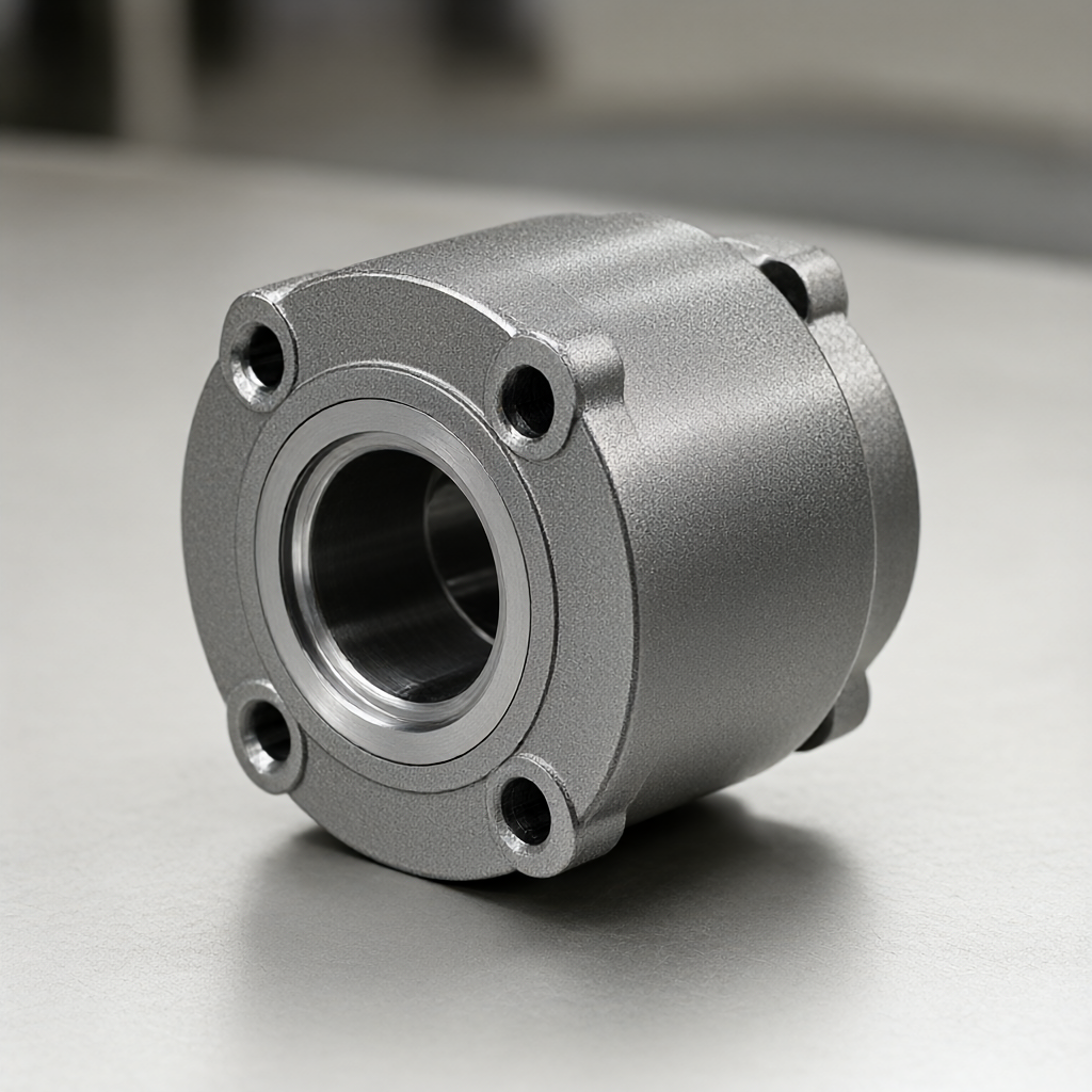
ShowyMetal pays special attention to appearance consistency in mass production. Through strict tool life management and tool breakage monitoring, it ensures that the surface finish of each shell is stable below Ra0.4μm, without cutting marks and scratches. For high gloss surface requirements, polishing or electrolytic treatment can be used, but it should be noted that these subsequent treatments may change the size and reverse tolerance is required. Roughness meter shall be used to spot check key mating surfaces in inspection process, and plug gauge shall be used to verify the through and stop state of bearing seat hole to ensure smooth assembly.
Batch Consistency Challenges and DFM Optimization Recommendations
DFM (Design for Manufacturability) recommends intervention at the drawing stage: relax the tolerances of non-mating surfaces to casting standards, and apply CNC finishing tolerances only to mating surfaces, sealing surfaces, and datum surfaces, which can significantly reduce machining costs and scrap rates.
In addition, it is recommended to optimize the runner position at the design end to keep it away from the critical mating surface and reduce the deburring depth. For deep cavity shells, sufficient tool withdrawal grooves should be reserved during design to prevent tool interference in the deep cavity. If turning and milling are used, axial and radial processes can be integrated to reduce clamping times and improve batch production efficiency. ShowyMetal has 72 CNC machines, including machine and milling complex, which can flexibly cope with the batch processing requirements of such complex structures and ensure the quality consistency from the first part to the last part.
FAQ: Technical Q & A on CNC deburring
What surface treatment is needed after deburring of joint reducer housing?
Anodic oxidation (AA12 or AA30) is generally recommended to enhance wear and corrosion resistance. Direct oxidation of the deburred finish results in better film adhesion. Blackening or electrophoretic coating is an option for a black appearance, but attention should be paid to the effect of coating thickness on size.
Can CNC deburring repair casting shrinkage?
No. Shrinkage is an internal defect and CNC machining can only remove surface and shallow defects. If shrinkage is located at a thin wall and close to the surface, it may be exposed during deburring and lead to scrap. Therefore, incoming inspection must use X-ray or ultrasonic inspection to ensure internal compactness.
How to determine how much processing allowance is appropriate for deburring?
Generally, it is more economical to reserve 0.5-1.0mm on one side. If the reservation is too large, it will increase cutting time and tool wear. If the reservation is too small, it may not be repaired due to casting size deviation. It is recommended to calculate the standard deviation of each size according to CMM report of foundry and dynamically adjust the allowance setting.
What are the advantages of 4-axis/5-axis machining over 3-axis machining in case deburring?
Multi-axis machining can realize continuous cutting of multiple surfaces in one clamping, avoiding accumulated errors caused by secondary positioning. For shells with oblique angles and special-shaped holes, multi-axis linkage can shorten tool stroke and improve accessibility, especially suitable for thin-walled structures that are easy to deform.
How to monitor the size stability of deburring in batch production?
SPC (Statistical Process Control) implementation is critical. Key size measurements (e.g. bearing bore diameter, concentricity) are taken from the first and last parts and intermediate parts of each batch, and control charts are drawn. Once the data points exceed the control limits, stop immediately to check tool wear or fixture looseness.
Conclusions and Guidelines for Cooperation
CNC deburring and finishing of joint reducer housing is the core link of balancing cost, precision and efficiency. Through scientific process path, reasonable parameter setting and strict appearance control, the reliability of transmission components can be significantly improved. ShowyMetal provides one-stop service from DFM advice, CNC machining to surface treatment with accuracy up to ±0.01mm and surface finish Ra0.4μm. If you have relevant drawings or samples, please send technical documents, we will provide targeted processing solutions and quotations based on specific structures to help you optimize product performance.