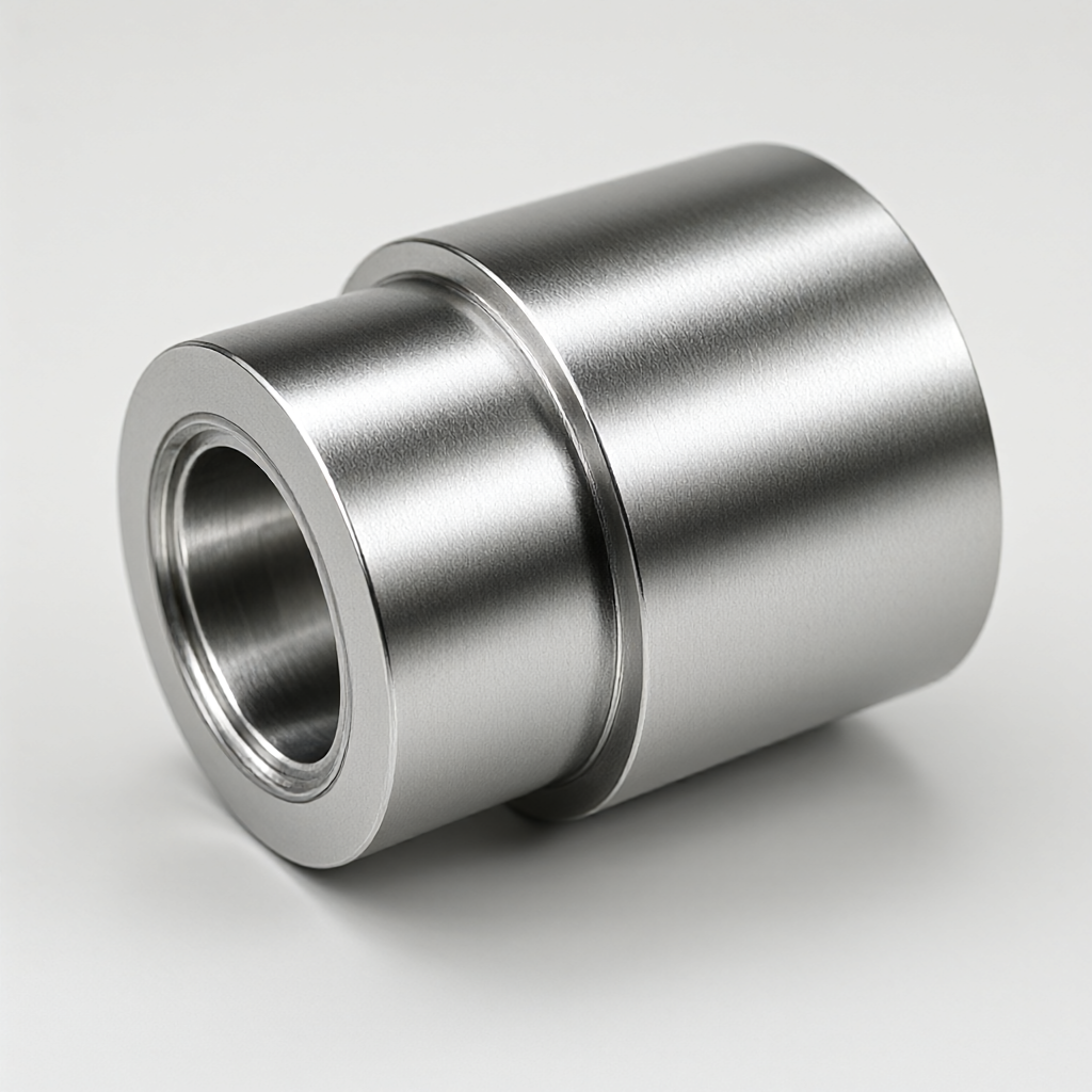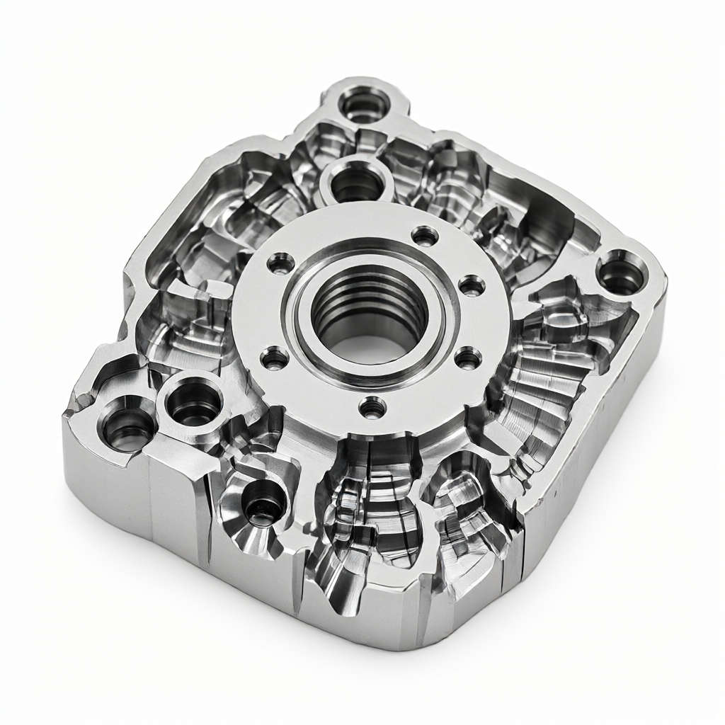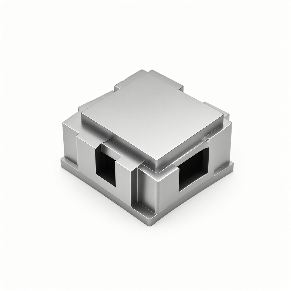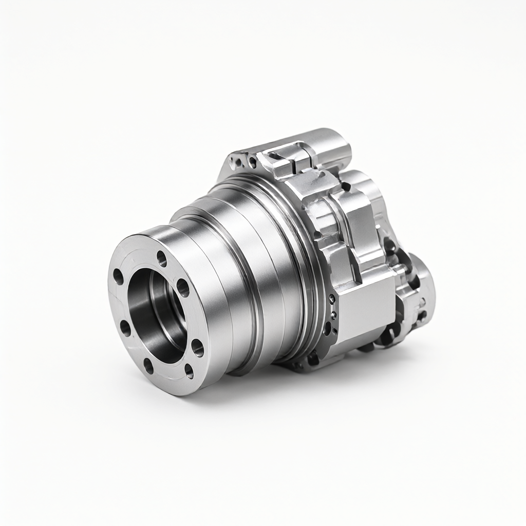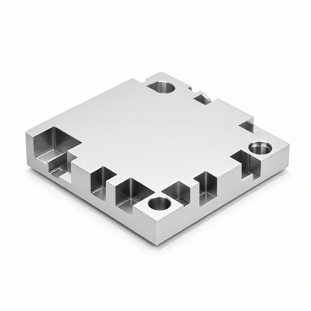
The aluminum heat sink base for photovoltaic inverters is precision-machined via CNC milling. The aluminum is cut to form a base with high thermal conductivity and efficient heat dissipation, working in conjunction with the inverter housing to achieve rapid heat removal. We support 6061, 6063, and 7075 series aluminum alloys, employing 3/4/5-axis CNC milling. Tolerances reach ±0.01 mm, with a surface finish of Ra0.4 μm. Dimensions, fin height, and hole positions can be customized per drawings. We also offer surface treatments such as anodizing, sandblasting, and hairline finishing, meeting the high requirements for heat dissipation efficiency and surface quality in photovoltaic inverters.
Specifications and Machining Capabilities: Materials, Dimensions, and Precision Standards for Aluminum Heat Sink Bases
- Common materials: 6061-T6 aluminum alloy (recommended; balances strength, thermal conductivity, and machining stability), 6063 aluminum alloy (high surface finish quality; suitable for appearance parts), 7075 aluminum alloy (high rigidity and strength; suitable for high power density applications).
- Machining size range: Typical base thickness 2–30 mm, width 20–800 mm, length 20–1000 mm; fin height 0.5–15 mm. Irregular contours, holes, countersinks, and chamfers can be customized per drawings.
- Dimensional tolerances: Critical mounting hole positions ±0.01 mm, base flatness ≤ 0.05 mm, fin height consistency ≤ ±0.02 mm.
- Surface finish: Base contact surface Ra0.4 μm to Ra0.8 μm; fin surface Ra0.8 μm to Ra1.6 μm. High gloss or sandblasted matte finishes available.
- Surface treatments: Anodizing (natural, black, color), sandblasting, hairline finishing, chemical polishing. Thermal insulating coating available as an option.
- Weight and wall thickness: Unit weight 0.1–8 kg; minimum fin wall thickness 0.5 mm, minimum hole diameter 1 mm.
Applicable Industries and Typical Applications: The Role and Positioning of Heat Sink Bases in PV Inverters
The aluminum heat sink base for photovoltaic inverters is typically installed between the inverter’s main control board (IGBT/SiC modules) and the housing, performing the critical function of rapidly conducting heat away from power devices. Specific application scenarios include:
- Heat sink bases for IGBT or SiC modules in string inverters and central inverters;
- Heat sink bases for power modules in commercial and industrial energy storage inverters;
- Shared heat sink structural components for the power and control stages in micro-inverters;
- Integrated heat sink support structures inside the inverter housing and on the power board.
This type of component has high requirements for base flatness, fin height consistency, and uniformity of anodized film thickness. CNC milling allows the base contour, holes, and fin forming to be completed in a single operation, reducing assembly steps and improving heat dissipation area efficiency.
Process and Equipment: CNC Milling, Surface Treatment, and Batch Consistency Control
Our 72 CNC machines include 3-axis, 4-axis, and 5-axis machining centers. The aluminum heat sink base for PV inverters is primarily milled using 3-axis vertical machining centers. 4/5-axis coordinated machining is used for taller fins or irregular structures to ensure fin angle and contour accuracy. The process path is as follows:
- Rough milling: Leave 0.2–0.3 mm stock to remove the bulk of material;
- Semi-finishing: 0.05–0.1 mm stock, controlling flatness;
- Finishing: Achieve final dimensions and fin shape, reaching Ra0.4 μm surface finish;
- Surface treatment: Anodizing or sandblasting to enhance corrosion resistance and appearance consistency;
- Inspection and shipping: Critical dimensions verified by CMM; 100% pre-shipment inspection.
Batch production uses program-controlled machining and first-article inspection to ensure dimensional, appearance, and anodized film thickness consistency across batches, reducing rework rates.
Capacity, Lead Times, and Customization Process: Complete Support from Drawing to Mass Production
For the aluminum heat sink base for PV inverters, we provide the following services:
- Prototyping lead time: Standard shapes 3–5 business days; complex irregular structures 7–10 business days;
- Batch lead time: Batch orders completed (production, surface treatment, and 100% inspection/shipping) within 15–25 days;
- Minimum order quantity: Prototyping supported from 1 piece; batch quantities flexibly arranged per customer needs;
- Customization support: Customized per customer drawings (CAD/STEP/IGS) or samples. Our engineering team provides DFM recommendations to optimize fin layout and hole positions, improving heat dissipation efficiency and reducing machining complexity.
Customization process: Submit drawings for quotation → Engineering evaluation and DFM recommendations → Prototype confirmation → Mass production scheduling → 100% inspection/shipping. The entire process utilizes CMM, optical measurement, and roughness testing equipment to ensure traceability of critical dimensions and surface quality.
FAQ: Common Procurement Questions About Aluminum Heat Sink Bases for PV Inverters
1. What tolerance can be achieved for the aluminum heat sink base for PV inverters?
Toleransen för viktiga monteringshål kan nå ±0,01 mm, planhets toleransen för basplattan är ≤ 0,05 mm, och höjdenivån för kylflänsar är ≤ ±0,02 mm, vilket uppfyller kraven för högupplöst montering.
2. Vilka yttekniker finns tillgängliga?
Tillgängliga alternativ inkluderar anodisering (naturlig, svart, färgad), sandstrålning, borstning och kemisk polering. Om en värmeledande material ska appliceras på ytan kan oxidering undvikas eller en tunn oxideringsyta användas, anpassad efter kundens specifikka krav.
3. Hur lång tid tar prototypering?
Prototypering för kylbaser med standardformer tar 3–5 arbetsdagar, medan komplexa icke-standardstrukturerna tar 7–10 arbetsdagar. Produktionsschemat kan anpassas efter projektets tidplan.
4. Hur lång tid tar massproduktion?
Leveranstiden för massorder är 15–25 dagar, inkluderande ytbehandling och sluttillverkning av varje enhet vid utfärd.
5. Kan flänsens höjd och hålets placering anpassas efter ritningen?
Javisst. Vårt ingenjörsstöd stöder anpassning av flänshöjd, hållplacering och basplattkontur baserat på CAD/STEP-ritningar och tillhandahåller DFM-förslag för att optimera strukturen.
Jämförelse av lösningar: CNC-fräsning vs extruderad aluminium kylbas
| Jämförelseparameter | CNC-fräsning (vår lösning) | Extruderad aluminium kylbas |
|---|---|---|
| Flexibilitet i form | Stödjer oregelbundna konturer, lokalt varierande flänshöjd och komplexa hål | Lämplig för regelbundna tvärsektioner; oregelbundna former kräver dyr formning |
| Minimal tjocklek | Minimal flänsväggstjocklek 0,5 mm | Vanligtvis ≥ 1,0 mm; tunna väggar riskerar att deformeras |
| Prototypleveranstid | 3–5 dagar (standard) | Kräver formning, vanligtvis 2–4 veckor |
| Massleveranstid | 15–25 dagar | 3–5 veckor (inklusive formning) |
| Ytikensformning | Dimensionell enhetlighet mellan batcher ≤ ±0,02 mm | Beroende av forms precision; något större variation mellan batcher |
| Lämplig fas | FoU, små serier, växling mellan flera modelltypor | Stor serieproduktion av en enskild modelltyp |
Solcellsomformare har snabb produktutveckling och många modelltyper. CNC-fräsning erbjuder markant snabare prototypering och strukturell flexibilitet, vilket lämpar sig för hela cykeln från FoU till massproduktion. Vi rekommenderar att ni skickar ritningar eller prototyper till oss; ingenjörsstöd kommer att lämna en tillverkningslösning och offert inom 24 timmar.