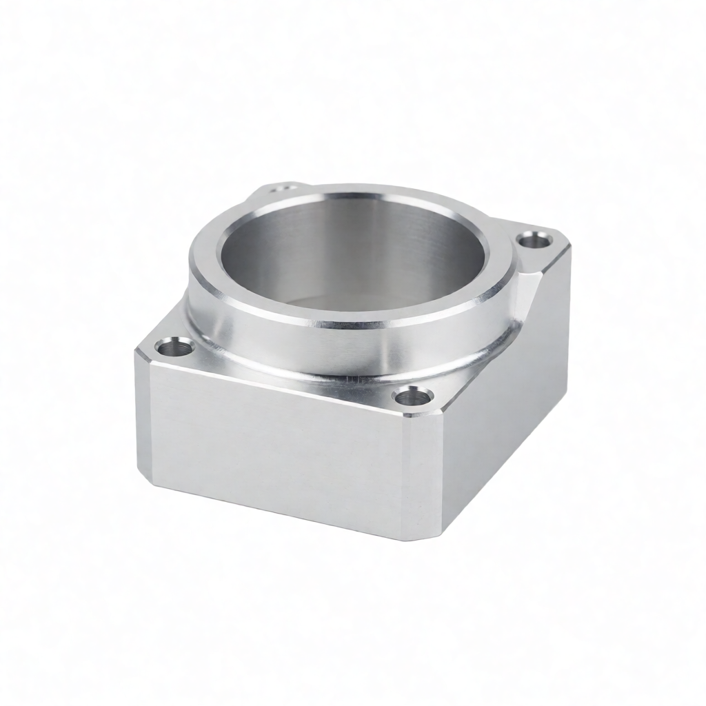
In the mass production of aluminum alloy parts, the design of fixtures for aluminum alloy machining directly determines the ability to consistently achieve a dimensional tolerance of ±0.01mm and a surface finish of Ra0.4μm. Many project delays or scrapping are not due to insufficient machine tool precision, but rather to uneven distribution of clamping force, improper selection of datum, or microscopic deformation caused by the release of residual thermal stress. For thin-walled parts, long shafts, or complex housings, a single setup is often insufficient to guarantee alignment in the three views; it is necessary to lock the geometric state through a logical locating-clamping sequence and pre-aging treatment of the material.
Mechanisms of Aluminum Alloy Cutting Deformation and Fixture Failure Modes
Aluminum alloys (especially common grades like 6061, 7075, and A5052) generate intense cutting heat and a plastic deformation layer during machining. If the fixture relies solely on contact at a few points, the part will undergo elastic recovery after stress release, leading to out-of-tolerance secondary machined surfaces or parallelism failure. Common fixture failure modes include:- Excessive elastic deformation: Thin-walled structures bend in the wall thickness direction under clamping force, with rebound quantities after unloading reaching 0.02-0.05mm, far exceeding standard tolerance ranges.
- Local crushing and scratches: Under high-gloss or mirror finish requirements, direct contact of hard alloy heads with machined surfaces causes microscopic damage, compromising appearance consistency.
- Thermal drift: The thermal expansion coefficient of aluminum alloy is approximately 23μm/m·K. If there is a large difference in thermal expansion between the fixture and the workpiece material and environmental temperature fluctuates, the locating datum will shift by microns.
Selection of Locating Datums and Application of the Six-Point Locating Principle
According to the Dreifuss six-point locating principle, aluminum alloy workpieces need to have six degrees of freedom removed. However, in CNC automated production, over-constraint leads to stress concentration, so "under-constraint" or "partial over-constraint" strategies are usually adopted, combined with the design of process datums.Unification of Process Datums and Measurement Datums
Locating datums should align as closely as possible with the main mating surfaces or functional surfaces on the design drawings. If not specified in the drawings, priority should be given to selecting the rigidest and largest flat surface as the primary locating surface (restricting Z-axis movement and X/Y-axis rotation), with secondary locating surfaces being two mutually perpendicular faces (restricting Y/Z-axis movement and Z-axis rotation). For example, when machining 6061-T6 aviation structural parts, if the bottom face is the mounting datum, a magnetic chuck or vacuum suction should be used to avoid mechanical clamping deformation; if there is a step on the side, a cylindrical pin locating system should be used, with pin diameter tolerance recommended as h7/g6 fit, ensuring repeatable positioning accuracy within 0.005mm.Floating Location and Adaptive Compensation
For multi-hole plate parts, due to large cumulative errors in hole spacing, rigid location easily leads to uneven clamping force. In this case, floating locating pins (such as a taper pin adaptive mechanism) should be used to automatically compensate for positional deviations within ±0.03mm, restricting only necessary degrees of freedom. On 5-axis machining centers, combined with probe measurement (Probing) to achieve adaptive tool setting, fixture cumulative errors can be further offset, raising batch consistency to a Cpk>1.67 level.Comparison of Clamping Methods: Mechanical, Vacuum, and Electromagnetic Solutions
Different clamping methods significantly affect the appearance and deformation of aluminum alloy. The choice criteria must consider part shape, batch size, surface quality requirements, and automated loading/unloading cycle times.| Clamping Method | Application Scenario | Deformation Control Capability | Surface Damage Risk | Automation Integration | Recommendation Rating | |
|---|---|---|---|---|---|---|
| Wedge Vise (Mechanical) | Regular rectangles, thick-walled parts | High (requires liners) | Medium (prone to leaving indentations) | High | ★★★ | |
| Vacuum Suction (Vacuum) | Thin plates, high finish, large flat surfaces | Very High (no point contact) | Low (requires sealing surface) | Very High | ★★★★★ | |
| Electromagnetic Chuck (Electromagnetic) | Magnetic materials (not suitable for pure aluminum) | — | — | Alta | Not applicable | |
| Dobras pneumáticos (Pneumatic Dowel) | Placas multifuradas, suportes de carga leve | Alta (pressão distribuída) | Baixa | Alta | ★★★★ | |
| Mandíbulas flexíveis (Soft Jaws) | Contornos irregulares, peças de geometria especial | Média (dependente da rigidez da mandíbula) | Baixa (amortecimento da camada de borracha) | Média | ★★★ |
Pontos práticos anti-deformação: Tratamento de envelhecimento e sequência de fixação
O design de fixação é uma solução estática; o controle dinâmico requer a integração com o pré-tratamento do material e a estratégia de programação.Eliminação de tensões residuais por tratamento de envelhecimento
Peças fundidas ou extrudadas de liga de alumínio possuem tensões residuais internas; a usinagem direta levará a deformações subsequentes incontroláveis. Para o material 6061, recomenda-se o tratamento T6 antes da usinagem CNC (estufagem 470-490℃×2-3h + resfriamento em água + envelhecimento artificial 190-200℃×7-8h) para liberar mais de 80% das tensões residuais. Se a estrutura da peça for complexa (como cavidades profundas, aletas finas), pode-se adotar o fluxo de três estágios "usinagem bruta - envelhecimento - usinagem final". Deixe 0.5-1.0mm de sobremetal na usinagem bruta; após a estabilização da liberação de tensões no envelhecimento, realize a fresagem final, o que garantirá a redução de mais de 50% na taxa de rejeição por desvio dimensional final.Lógica de fixação multioperação e ruptura da cadeia de erros
Para eixos ou carcaças com relação comprimento/diâmetro superior a 10:1, a fixação única não garante a concentricidade em todo o comprimento. Deveria-se usar a combinação de "posicionamento por furos centrais em ambas as extremidades" ou "trava em V + centro". Em máquinas de 4/5 eixos, a rotação do quarto eixo permite a usinagem de múltiplas faces em uma única fixação, reduzindo o número de trocas de referência. O erro acumulado introduzido a cada troca de referência é de aproximadamente 0.01-0.02mm, portanto, quanto menos operações, maior a precisão total. Simultaneamente, o caminho da ferramenta deve seguir o princípio de "primeiro externo depois interno, primeiro bruto depois fino, corte simétrico", de modo que as tensões residuais sejam distribuídas simetricamente, cancelando-se mutuamente.Temperatura ambiente constante e equilíbrio térmico
A oficina de usinagem de ligas de alumínio de precisão deve manter uma temperatura e umidade constantes de 20±1℃. Após os fixadores e as peças saírem da área de armazenamento para a máquina, precisam de 30-60 minutos para equilíbrio térmico, evitando deformações térmicas causadas por diferença de temperatura. Para peças de alto valor em lotes, recomenda-se a configuração de um sistema de fixação com temperatura constante, controlando a temperatura da base do fixador na faixa de 18-22℃, sincronizada com a temperatura da peça.Padrões de aceitação: Inspeção CMM e consistência estética
A validação final do design do fixador depende dos dados de inspeção do laboratório de metrologia terceirizado ou interno.- Tolerância dimensional: Tolerância de ±0.01mm para superfícies de encaixe críticas, usando uma máquina de medição tridimensional de alta precisão (CMM, resolução 0.5μm) para varredura dimensional completa, com espaçamento entre pontos ≤0.5mm, garantindo que os erros geométricos (planicidade, paralelismo) estejam dentro dos requisitos da engenharia.
- Rugosidade da superfície: Superfície visual Ra0.4μm, medida com um perfilômetro de ponta de contato (como Mitutoyo Surftest), comprimento de amostragem 2.5mm, tomando a média de 3 direções. Sem riscos, sem lascas; o efeito espelhado deve ser confirmado por comparação visual com amostras de referência.
- Consistência do lote: Selecione a primeira, a intermediária e a última peça, mais 10 peças aleatórias, e calcule o desvio padrão (SD) das dimensões críticas, exigindo Cpk ≥ 1.33. Se Cpk < 1.0, é necessário rastrear causas como desgaste dos pinos de posicionamento do fixador ou flutuação da força de fixação.
- Verificação de dureza: Para a liga de alumínio 7075-T6, a dureza deve ser de 95-150 HRB, usando um dureômetros para inspeção por amostragem, evitando deformação por deflexão da ferramenta devido à queda de resistência causada por envelhecimento insuficiente.